
Manufacturer
Custom
Metal-cased
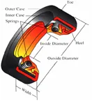
Rotary seals
SEAL TYPES
Critical Seal Design Tolerance Charts
By: Owen McGuiness Independence Seal Gibsonia, PA
Recommended shaft and bore tolerances
It is almost impossible, in practice, to manufacture seal components with absolute dimensional accuracy; actual production parts may vary slightly from dimensional drawings. Given this fact, it becomes necessary that the nominal dimensions of critical contact points fall within certain acceptable ranges to allow for reliable operation.
These tolerances for nominal diameters are published by the Rubber Manufacturers Association and are in use by most major seal manufacturers. The tolerances recognize for instance, one critical point of contact in a shaft seal as the point between the seal OD and the housing bore. Shaft seals are typically press fit into a housing bore and to ensure a snug fit, the seal OD is produced larger than the housing bore. Typically, metal OD seals are .004″ to .008″ larger than the bore and rubber-covered OD’s .006″ to .012″ larger than the bore depending on the bore size. Rubber-covered OD’s are larger because the rubber OD needs to generate sufficient interference or sealing force between the OD and bore to prevent leakage and “creep” or movement of the seal within the bore. When designing or installing a shaft seal, the bore and seal OD tolerances should be considered to ensure proper equipment operation and reduce down time. The following table represents the recommended tolerances between bore and seal OD for a bore made from ferrous materials* operating under normal conditions.
Bore & Seal OD Tolerance Table Metric
| Bore Diameter (millimeters) | Tolerance (millimeters) | Metal OD 1 | Rubber Covered OD 1 | ||
|---|---|---|---|---|---|
| OD Tolerance | Max OOR | OD Tolerance | Max OOR | ||
| diameter ≤ 50 | +0.039 | +0.20 | 0.18 | +0.30 | 0.25 |
| -0.00 | +0.08 | +0.15 | |||
| 50 to ≤ 80 | +0.046 | +0.23 | 0.25 | +0.35 | 0.35 |
| -0.00 | +0.09 | +0.20 | |||
| 80 to ≤ 120 | +0.054 | +0.25 | 0.30 | +0.35 | 0.50 |
| -0.00 | +0.10 | +0.20 | |||
| 120 to ≤ 180 | +0.063 | +0.28 | 0.40 | +0.45 | 0.65 |
| -0.00 | +0.12 | +0.25 | |||
| 180 to ≤ 300 | +0.075 | +0.35 | Up to 25% of diameter | +0.50 | 0.80 |
| -0.00 | +0.15 | +0.25 | |||
| 300 to ≤ 440 | +0.084 | +0.45 | Up to 25% of diameter | +0.55 | 1.00 |
| -0.00 | +0.20 | +0.30 | |||
| Source: Rubber Manufacturers Association | |||||
Seal OD is determined by averaging at least three measurements taken at equally spaced positions * For housing bores made of aluminum or other non-ferrous materials consult Colonial Seal Company for recommendations.
Bore & Seal OD Tolerance Table Inches
| Bore Diameter (inches) | Tolerance (inches) | Metal OD 1 | Rubber Covered OD 1 | ||
|---|---|---|---|---|---|
| OD Tolerance | Max OOR | OD Tolerance | Max OOR | ||
| diameter ≤ 2.00 | ± 0.001 | ± 0.002 | 0.007 | ± 0.003 | 0.010 |
| 2.00 to ≤ 3.00 | ± 0.001 | ± 0.0025 | 0.010 | ± 0.003 | 0.014 |
| 3.00 to ≤ 5.00 | ± 0.0015 | ± 0.003 | 0.012 | ± 0.003 | 0.020 |
| 5.00 to ≤ 7.00 | ± 0.0015 | ± 0.003 | 0.016 | ± 0.004 | 0.026 |
| 7.00 to ≤ 12.00 | ± 0.002 | ± 0.0035 | 0.0025 | ± 0.004 | 0.031 |
| 12.00 to ≤ 20.00 | ± 0.003 | ± 0.005 | 0.0025 inch per inch of seal OD | ± 0.005 | 0.039 |
| 20.00 to ≤ 40.00 | ± 0.004 | ± 0.005 | ± 0.006 | 0.045 | |
| diameter ≥ 40.00 | ± 0.006 | ± 0.006 | ± 0.007 | 0.050 | |
| Source: Rubber Manufacturers Association | |||||
Seal OD is determined by averaging at least three measurements taken at equally spaced positions
As mentioned above, the manufacturing process many not produce perfectly round or circular housing bores, seal OD’s or shafts. The variance in the radial profile from perfectly circular is referred to as out-of-round. Even with the proper press fit, leakage can still occur between the housing bore and seal OD if there is excessive out-of-roundness. The maximum out-of-round (OOR) tolerance listed above represents the RMA recommended maximum variance of the actual profile from perfect roundness that should be considered.
Another contact point critical to the performance of a seal occurs where the seal lip and shaft contact. The interference between the shaft and sealing lip is greatly affected by a number of factors including shaft speed, hardness, materials and operating pressures. For instance, a high-speed shaft will require a lower interference to minimize drag and heat caused by friction. To assist equipment engineers and seal manufacturers the RMA has published standard shaft diameter tolerances to ensure satisfactory performance of a rotary seal.
Shaft Diameter Tolerances
| Shaft Diameter (millimeters) | Tolerance (millimeters) | Shaft Diameter (inch) | Tolerance (inch) |
|---|---|---|---|
| diameter ≤ 100 | ± 0.08 | diameter ≤ 4.00 | ± 0.003 |
| 100 to 150 | ± 0.10 | 4.00 to 6.00 | ± 0.004 |
| 150 to 250 | ± 0.13 | 6.00 to 10.00 | ± 0.005 |
| diameter > 10.00 | ± 0.010 | ||
| Source: Rubber Manufacturers Association | |||
Lip ID Tolerances
| Lip Diameter (millimeters) | Tolerance (millimeters) | Lip Diameter (inch) | Tolerance (inch) |
|---|---|---|---|
| diameter ≤ 75 | ± 0.50 | diameter ≤ 3.00 | ± 0.02 |
| 75 to ≤ 150 | ± 0.65 | 3.00 to ≤ 6.00 | ± 0.025 |
| 150 to ≤ 250 | ± 0.75 | 6.00 to ≤ 10.00 | ± 0.03 |
| Source: Rubber Manufacturers Association | |||
The recommendations given above are for general purpose applications operating under normal conditions. Applications for harsh environments or high operating pressure and rotating speeds, please consult your seal manufacturer or Independence Seal for recommendations.
References
Brink, Robert. Handbook of Fluid Sealing. McGraw Hill. 1993 Horve, Les. Shaft Seals for Dynamic Application. New York ; CRC. 1996 Rubber Manufacturers Association. EPG Group; Washington DC SEA Fluid Sealing Handbook. 1996 Edition